
Construction process
Building a vinyl liner pool with concrete walls
From excavation to liner track: the vinyl liner pool construction process with the Swim-crete forming system, step by step.
General guidance only. These steps describe how the Swim-crete forming system is typically used. They are not a substitute for engineered plans, the Swim-crete pool prints for your project, or your local building codes.
-
 01
01Excavation
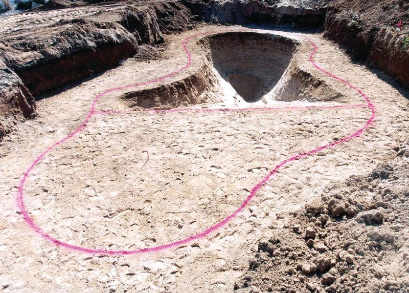
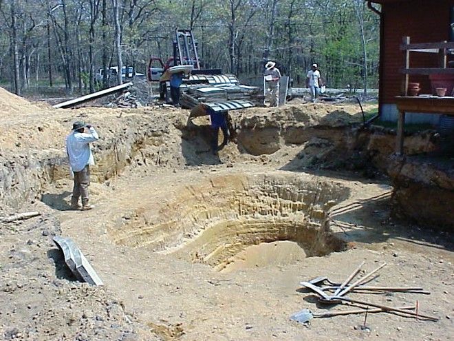
Commonly an inside 6″ lip is part of the over dig. The purpose of this lip is to allow working room for setting of forms. Once forms are set and concrete placed, cut this lip away when shaping the hopper. Also, the working shelf should be as level as possible for the setting of the concrete forms.
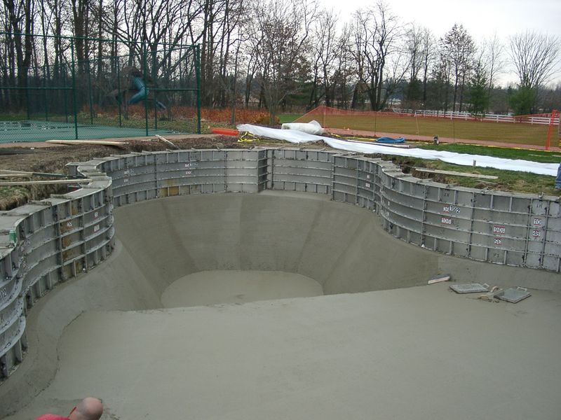
The excavated depth of the hopper should be 9″ to 12″ deeper than the specified finished depth to compensate for the material used for surfacing the bottom and hole shaping.
-
 02
02Setting forms
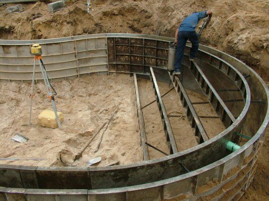
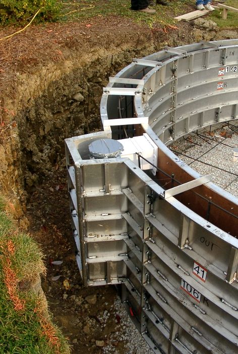
Once the shelf is prepared, lay out forms, both inside and outside. Utilizing the Swim-crete pool prints, start with the step forms. Step forms should be set and level prior to setting any wall forms. When step forming is complete, begin setting wall. Walls can be set from both sides of the step system to enable closing of forms at opposite end of pool.
-
 03
03Steps — concrete
Steps should always be set first when utilizing the Swim-crete concrete step system. Refer to step prints for form placement of the particular step design you are utilizing.
-
 04
04Steps — fiberglass
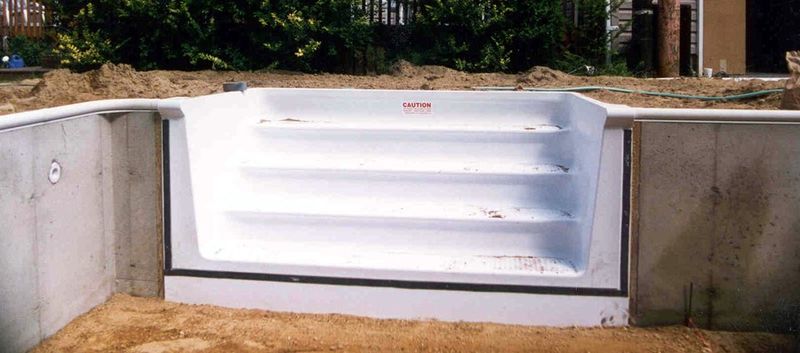
Fiberglass steps may also be used with the Swim-crete system. If using a fiberglass step kit, use two C.C.A. treated 2x10’s with lag bolts to secure step system to lumber, ensuring bolts protrude into space that will be poured in concrete. This will allow for anchoring into concrete wall.
-
 05
05Squaring & leveling
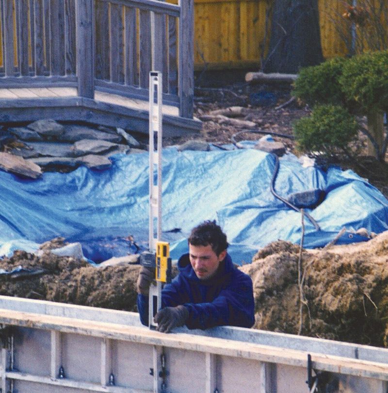
To determine if your pool is square, check your pool print for proper squaring dimension, adjust as needed. Shoot to the top of the forms using a laser or transit to establish highest point of pool. Start from the opposite end of the pool using shims to level towards high point until pool is level.
-
 06
06Placing concrete
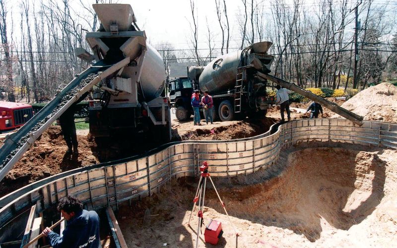
After the form system is level and square, check all inlet fittings, skimmers, light housing and tie placement to ensure they are secured properly. Then concrete is ready to be placed. Recommended concrete is a minimum of 3,000 psi, 3″ slump mix for steps. Once concrete steps are poured, increase concrete slump to desired flowability for wall area. For concrete yardage refer to Swim-crete pool prints.
-
 07
07Wall foam
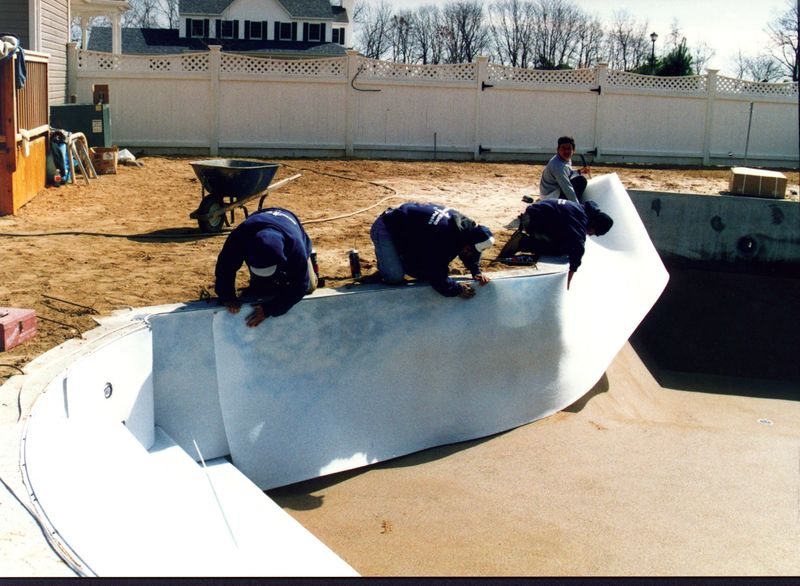
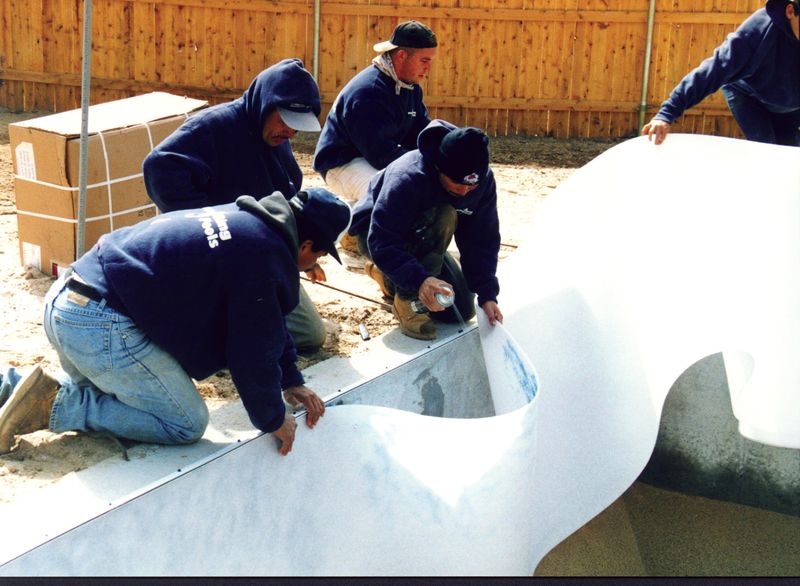
While Swim-crete aluminum forming system pours a smooth wall with minimal seams, it is recommended to foam the walls to protect the vinyl liner from needless wear. When the Swim-crete step system is incorporated into the pool it is also recommended to apply foam, if it is to be vinyl lined.
Using spray adhesive, spray the walls and attach the foam shape and smooth bottom of pool, eliminating any ledge that may be left where pool wall and floor meet.
-
 08
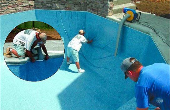
08Track and vinyl liner installation
Swim-crete recommends using Aluma-Trac liner track (aluminum track). This can be installed by drilling into the top of the wall using a standard hammer drill and attaching with stainless steel concrete screws, or by simply nailing the track on the day after the finished pour with concrete nails. If using a plastic track retainer, it can be poured in place and the track attached to it.
Sales & engineering
Talk to a regional manager
National, Eastern and international sales, plus the engineering department that draws the layouts. One form, or one call.